
A logic gate applies a rule to one or more binary inputs and produces a binary output. A truth table writes down that rule for every possible input combination. Read the table as a complete specification of an ideal Boolean function, rather than a list of events happening in time.
We will use 0 and 1 throughout this explanation. In a physical circuit, these symbols represent ranges of voltage accepted as low and high. They are not instructions to connect any particular voltage to an arbitrary device. Electrical limits belong to the device's data sheet.
Start with all the possibilities
For two inputs, A and B, there are four combinations: 00, 01, 10 and 11. Listing them in that order makes missing cases easy to spot. Neither input is more important; the order is simply a useful convention for reading and checking the table.
If your output column has only three rows, your description is incomplete. You have left one possible situation unspecified. This habit scales: three binary inputs require eight rows, because each new input doubles the number of combinations.
AND means both conditions hold
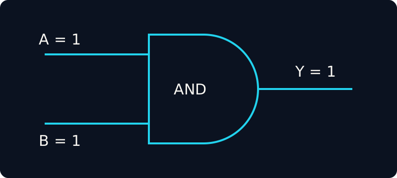
Both conditions are met. Original simplified educational diagram by Chiprion.
A two-input AND gate produces 1 only when A and B are both 1. Imagine an illustrative permission signal: a machine may start only when a request is present and its guard is closed. If either condition is absent, permission is 0. This example explains a Boolean rule; it is not a complete safety-control design.
| A | B | A AND B |
|---|---|---|
| 0 | 0 | 0 |
| 0 | 1 | 0 |
| 1 | 0 | 0 |
| 1 | 1 | 1 |
Notice that changing B while A remains 0 does not change the result. The missing A condition is enough to keep the output at 0. A good way to remember AND is to ask, “Have all required conditions been met?”
OR means at least one condition holds
A two-input OR gate produces 1 when A is 1, B is 1, or both are 1. Suppose two independent requests can illuminate an indicator. An OR rule turns that indicator on for either request and keeps it on when both requests arrive.
| A | B | A OR B |
|---|---|---|
| 0 | 0 | 0 |
| 0 | 1 | 1 |
| 1 | 0 | 1 |
| 1 | 1 | 1 |
The last row matters. Everyday language sometimes uses “or” to mean exactly one choice. Boolean OR includes the case where both inputs are 1. The “exactly one of two” function has a different name: exclusive OR, or XOR.
NOT reverses one bit
NOT has one input. It produces 1 for an input of 0 and 0 for an input of 1. Its truth table therefore needs only two rows.
| A | NOT A |
|---|---|
| 0 | 1 |
| 1 | 0 |
If a signal named busy is 1 while a resource is occupied, NOT busy can express its Boolean opposite. Naming is part of understanding the logic: “available” is often easier to reason about than an unexplained inverted symbol. Always check what a signal's 1 actually means before combining it with another signal.
Work through a combined rule
Consider a simplified indicator rule: turn on a light when either request A or request B is present, provided that an inhibit input I is 0. Write the relationship in two steps so that the role of each gate is explicit.
request_present = A OR B
light = request_present AND (NOT I)
This is Boolean pseudocode, not a hardware-language program. Try A = 0, B = 1 and I = 0. The first line gives 1. NOT I also gives 1. The final AND therefore gives light = 1. Keep A and B unchanged but set I to 1: the last operation becomes 1 AND 0, so light becomes 0.
Try it yourself
For that same rule, find the light output for these three cases: A = 0, B = 0, I = 0; A = 1, B = 1, I = 0; and A = 1, B = 0, I = 1. Work through the intermediate request_present value before reading the answer.
Answer: the outputs are 0, 1 and 0 respectively. In the first case no request exists. In the second case both requests exist and inhibit is absent. In the third case inhibit blocks the request. A complete three-input table would include five more cases.
What the table leaves out
A truth table describes the logical relationship after signals have settled. It does not promise that a physical output changes instantly, specify propagation delay, or show temporary glitches during input transitions. Keep those timing questions separate from the Boolean rule. Start by making the rule complete; then use the relevant device specifications and timing analysis to understand its implementation.
Try the inputs
Output Y = 0Both inputs must be 1 for the output to be 1.
| A | B | Y = A AND B |
|---|---|---|
| 0 | 0 | 0 — current inputs |
| 0 | 1 | 0 |
| 1 | 0 | 0 |
| 1 | 1 | 1 |
Explore related programmes
These recorded programmes are upcoming. This article is general educational content, not a syllabus or course sample.
Digital ElectronicsVerilog